|
|
||||
| Small Cell ODA 65°x65° Antenna | ODA65F-KE1A |
|||

 Pattern Viewer
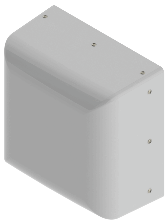 |
 |
|
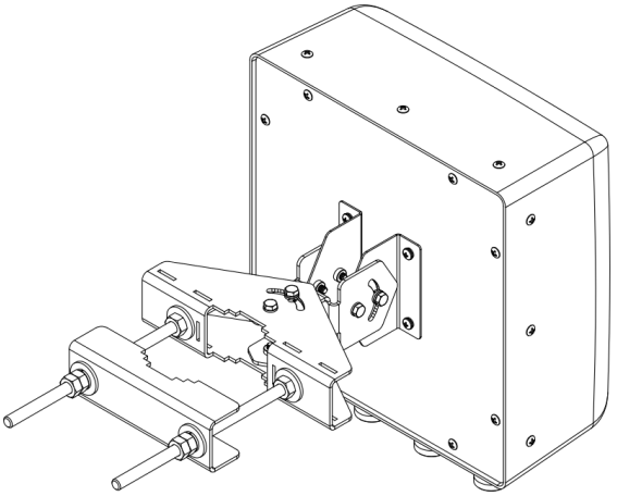
Mechanical
| Dimensions (L×W×D) | 11.8×11.8×6.1 in (300×300×156 mm) |
| Survival Wind Speed | > 125 mph (> 201 kph) |
| Front Wind Load | 30 lbs (132 N) @ 100 mph (161 kph) |
| Side Wind Load | 15 lbs (69 N) @ 100 mph (161 kph) |
| Equivalent Flat Plate Area | 1.2 ft2 (0.1 m2) |
| Weight* | 4.6 lbs (2.1 kg) |
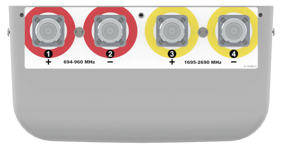
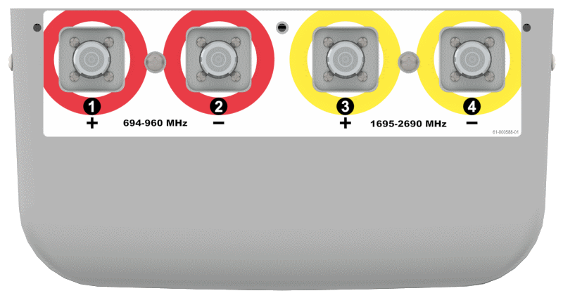
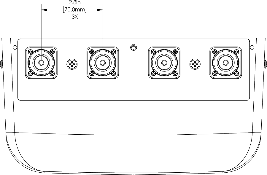
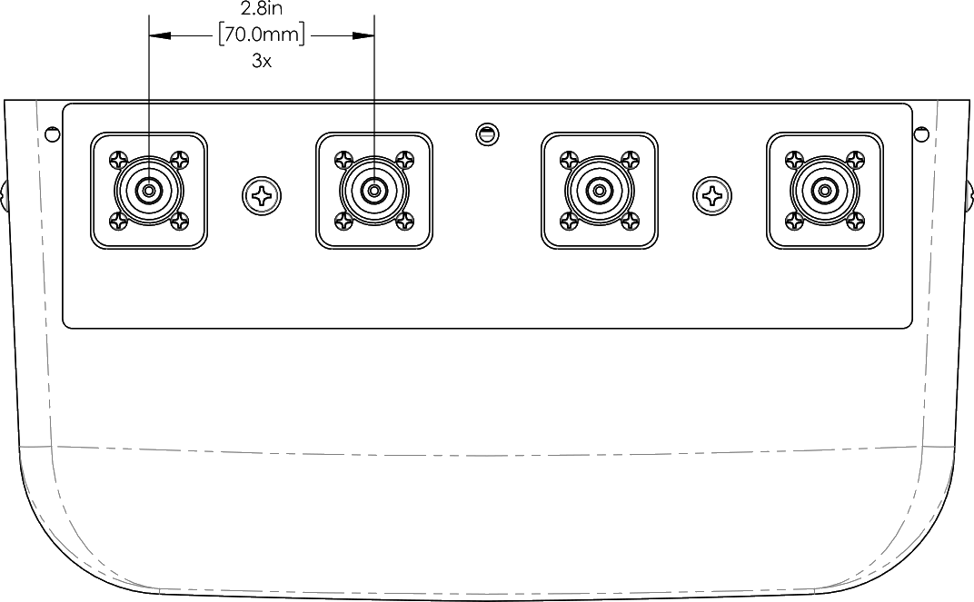
| Connector | 4 × 7-16 DIN female long neck or 4.3-10 Female |
| Wall Mount (fixed) | 0.375 in (10 mm) diameter hardware recommended |
| Wall Mount Tilt | 0.375 in (10 mm) diameter hardware recommended |
| Mounting Pole | 2 to 4.5 in (5 to 11 cm) |
| * Weight excludes mounting |
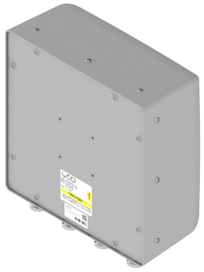
| Bottom View | ODA65F-KE1AA | ODA65F-KE1AB |
 |
 |
|
| Connector Spacing | ODA65F-KE1AA | ODA65F-KE1AB |
 |
 |
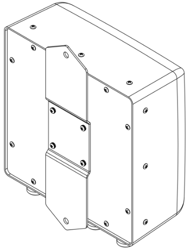
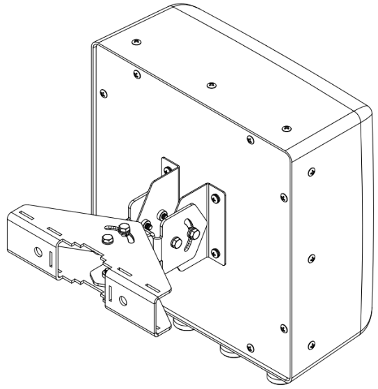
| Mounting Kit Views | |||
 |
 |
 |
|
| MBK-09 | MBK-08 | MBK-08 with optional MBC-07 |
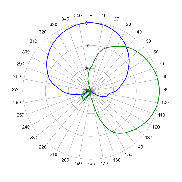
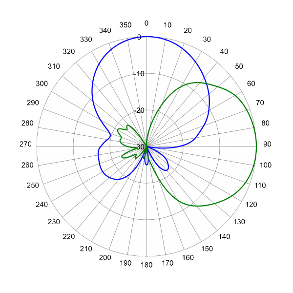
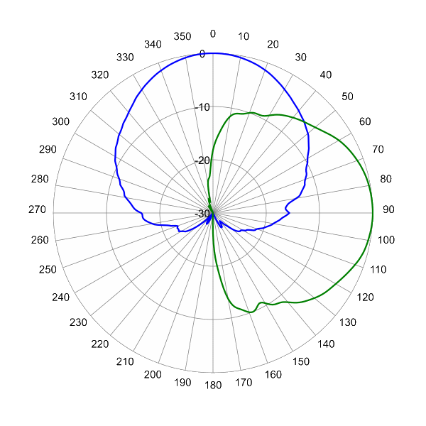
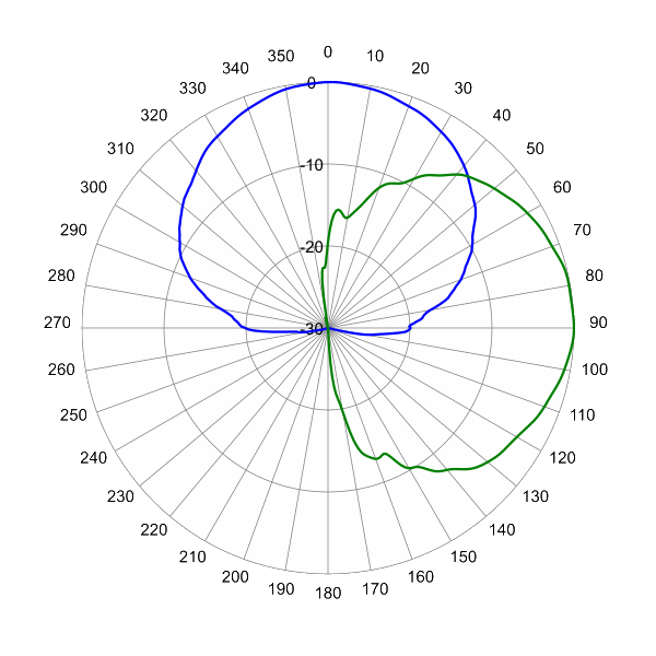


Antenna Pattern