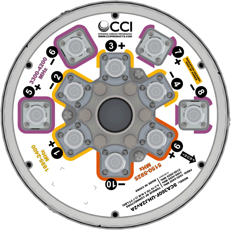
| Ports |
4 × High Band Ports for 1695-2400 MHz |
| Frequency Range |
1695-1880 MHz |
1850-1990 MHz |
1920-2180 MHz |
2300-2400 MHz |
| Gain1 (2° EDT) |
8.2 dBi |
8.3 dBi |
8.4 dBi |
8.7 dBi |
| Gain1 (6° EDT) |
8.2 dBi |
8.3 dBi |
8.5 dBi |
8.5 dBi |
| Gain1 (10° EDT) |
8.2 dBi |
8.2 dBi |
8.6 dBi |
8.6 dBi |
| Gain1 (13° EDT) |
8.0 dBi |
8.0 dBi |
8.6 dBi |
8.5 dBi |
| Gain (Average)2 (2° EDT) |
7.7 dBi |
8.0 dBi |
8.1 dBi |
8.3 dBi |
| Gain (Average)2 (6° EDT) |
7.8 dBi |
8.0 dBi |
8.1 dBi |
8.3 dBi |
| Gain (Average)2 (10° EDT) |
7.7 dBi |
7.9 dBi |
8.1 dBi |
8.3 dBi |
| Gain (Average)2 (13° EDT) |
7.2 dBi |
7.5 dBi |
7.9 dBi |
8.0 dBi |
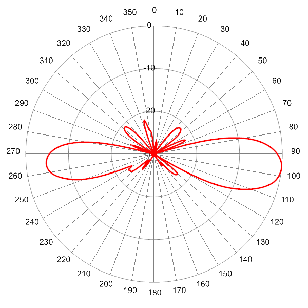
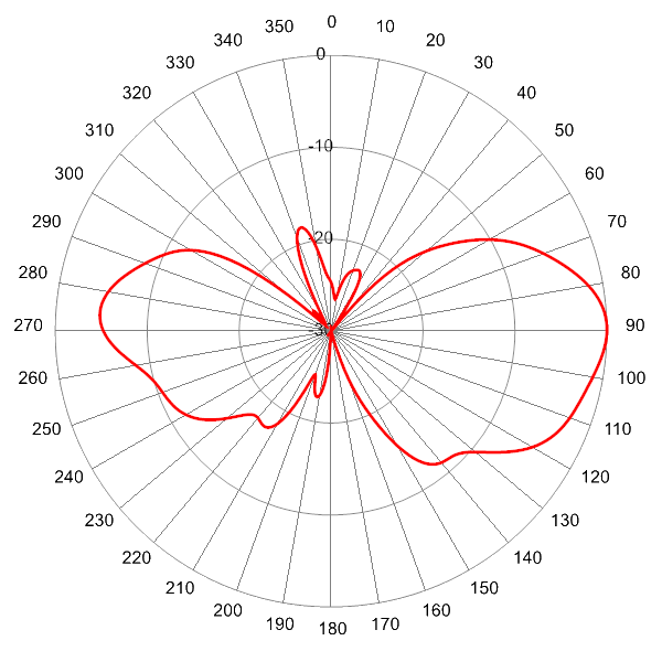
| Elevation Beamwidth (-3dB) (2° EDT) |
26.1° |
24.0° |
23.2° |
19.7° |
| Elevation Beamwidth (-3dB) (6° EDT) |
25.7° |
24.5° |
23.7° |
20.3° |
| Elevation Beamwidth (-3dB) (10° EDT) |
26.0° |
24.5° |
23.9° |
20.0° |
| Elevation Beamwidth (-3dB) (13° EDT) |
25.8° |
25.2° |
23.9° |
21.0° |
| Electrical Downtilt |
2° or 6° or 10° or 13° |
| First Upper Sidelobes (at Peak Gain) (2° EDT) |
< -20 dB |
< -18 dB |
< -18 dB |
< -18 dB |
| First Upper Sidelobes (at Peak Gain) (6° EDT) |
< -18 dB |
< -18 dB |
< -20 dB |
< -18 dB |
| First Upper Sidelobes (at Peak Gain) (10° EDT) |
< -18 dB |
< -17 dB |
< -17 dB |
< -18 dB |
| First Upper Sidelobes (at Peak Gain) (13° EDT) |
< -17 dB |
< -14 dB |
< -14 dB |
< -13 dB |
| Cross-Polar Port-to-Port Isolation (all tilts) |
> 25 dB |
| Interband Port to Port Isolation (all tilts) |
> 25 dB |
| Voltage Standing Wave Ratio(VSWR) |
< 1.5:1 |
| Passive Intermodulation (2×20W) |
≤ -153 dBc |
| Input Power Continuous Wave (CW) |
200 watts |
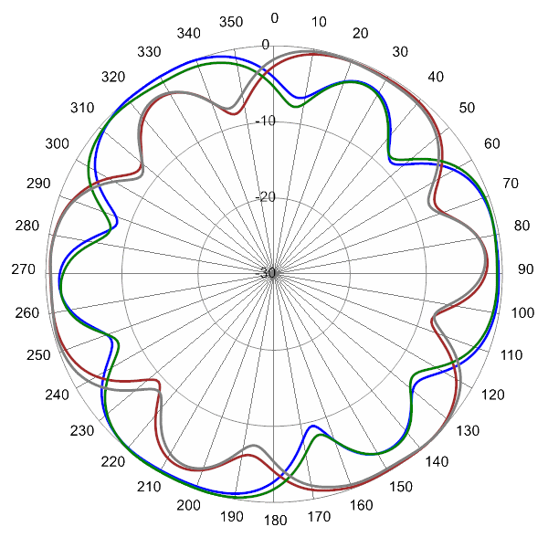
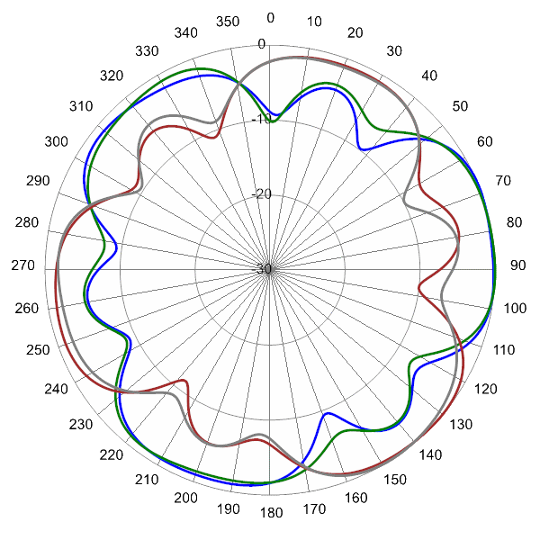
| Polarization |
Dual Pol 45° |
| Input Impedance |
50 ohms |
| Lightning Protection |
DC Ground |
1Peak gain across sub-bands.
2Electrical specifications follow document "Recommendation on Base Station Antenna Standards" (BASTA) V9.6. |


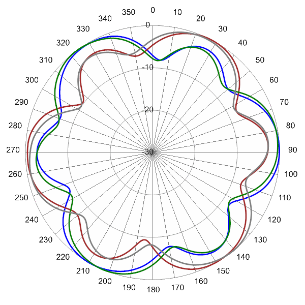
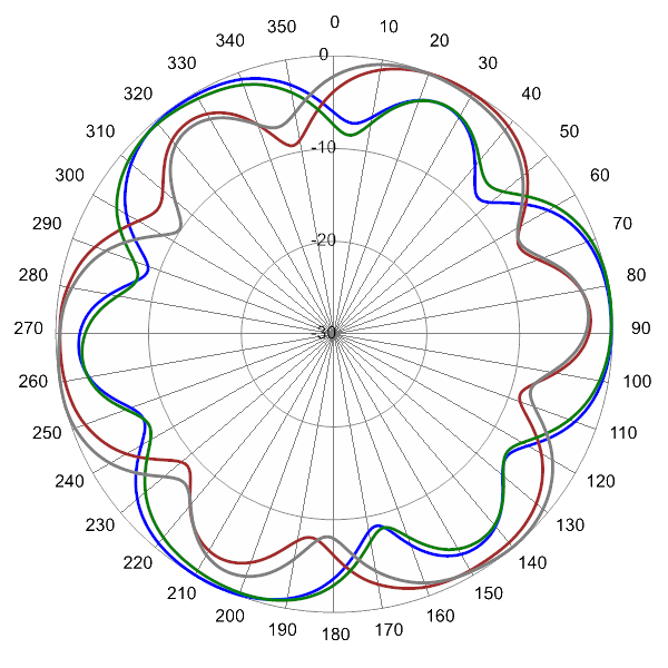
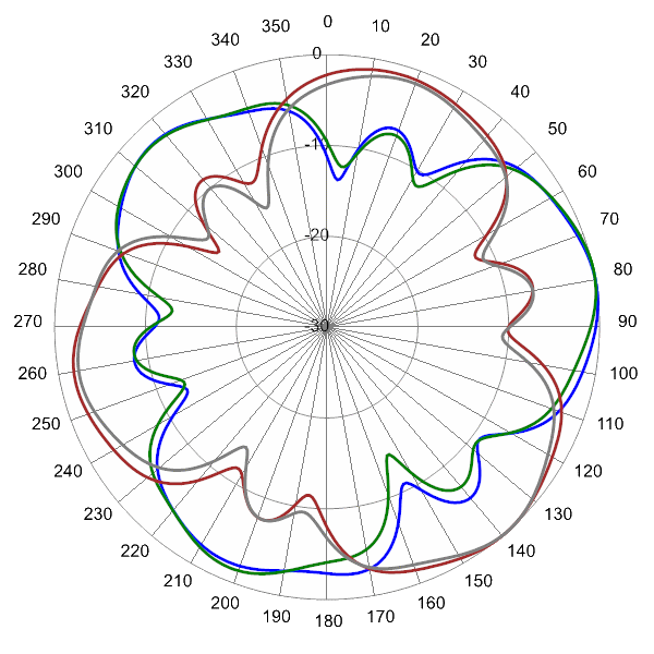
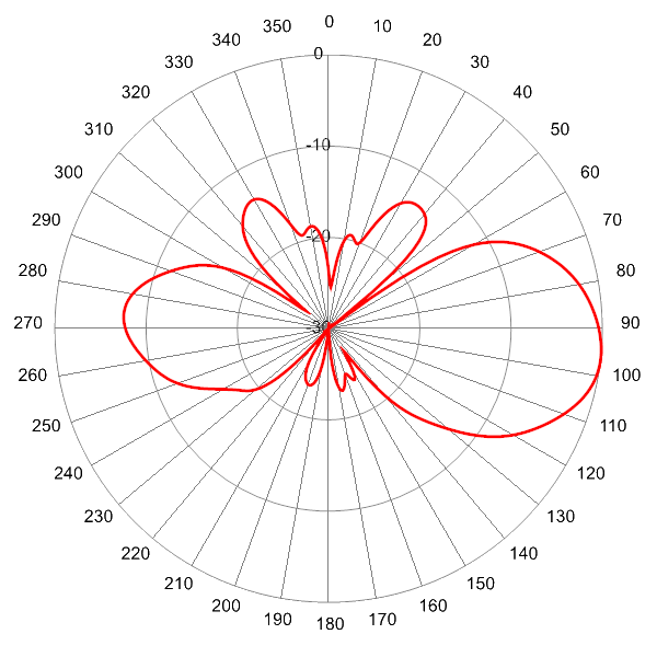
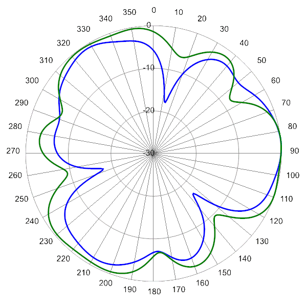
 Pattern Viewer
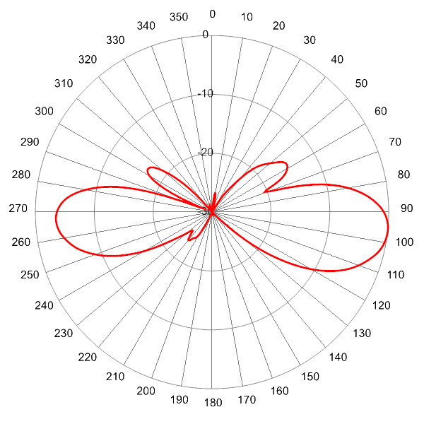
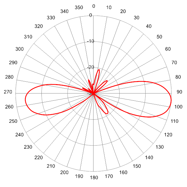
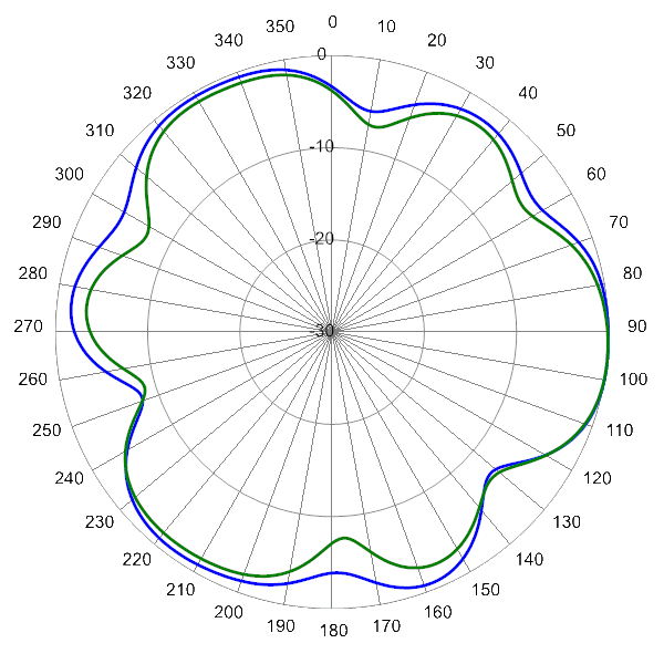
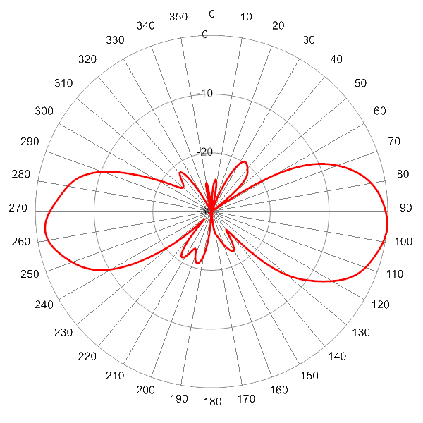
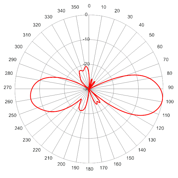