|
|
||||
| Tri-Band Eight Port Antenna | OPA65R-TE6C | |||

 Pattern Viewer
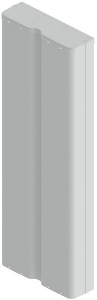 |
 |
|
||
Mechanical
| Dimensions (L×W×D) | 71.2×25.5×8.1 in (1808×648×205 mm) |
| Survival Wind Speed | > 150 mph (> 241 kph) |
| Front Wind Load | 392 lbs (1742 N) @ 100 mph (161 kph) |
| Side Wind Load | 149 lbs (664 N) @ 100 mph (161 kph) |
| Equivalent Flat Plate Area | 15.3 ft2 (1.4 m2) |
| Weight * | 78.6 lbs (35.7 kg) |
| Connector | 8 × 4.3-10 female |
| Package Dimensions (LxWxD) | 80.3x30.2x14.4 in (2040x766x366 mm) |
| Package Weight | 129.0 lbs (58.5 kg) |
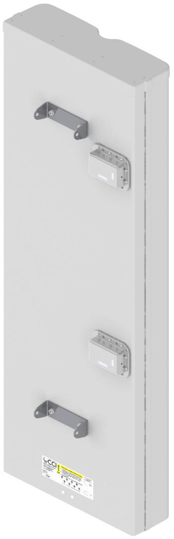
| Mounting Pole | 2 to 5 in (5 to 12 cm) |
| * Weight excludes mounting |
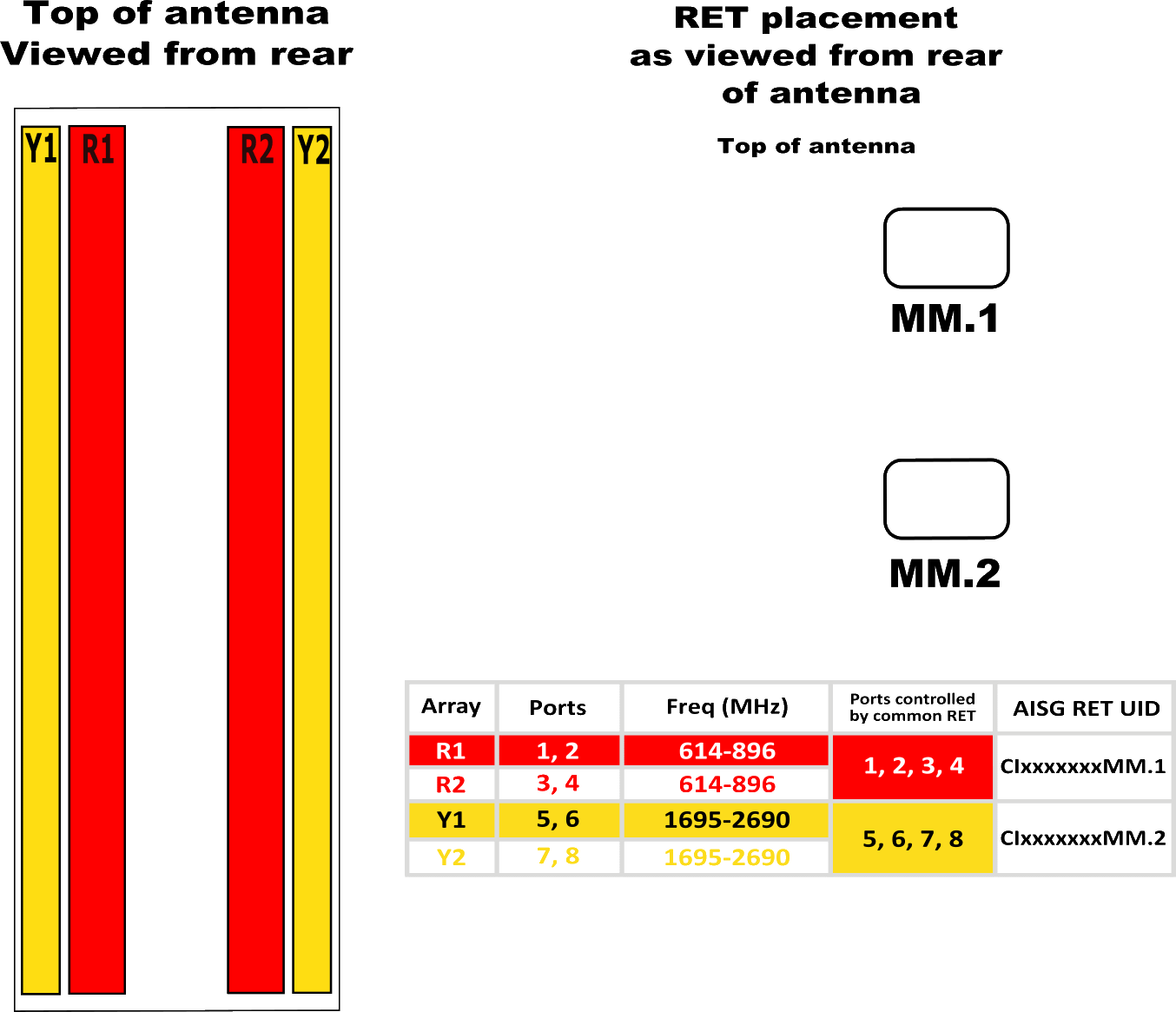
| Bottom View | OPA65R-TE6CA (Type 17 Internal RET) |
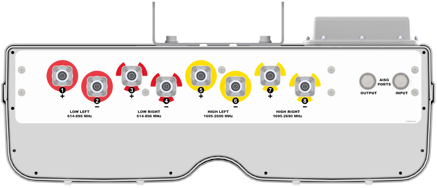 |
| Connector Spacing | |
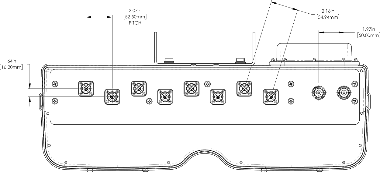 |
| RET to Element Configuration | OPA65R-TE6CA Element and RET configuration (Type 17 Internal RET) |
 |
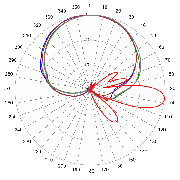
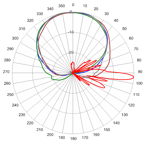
Typical Antenna Patterns
| For detailed information on additional antenna patterns, contact customer support at | ||
 |
 |
|
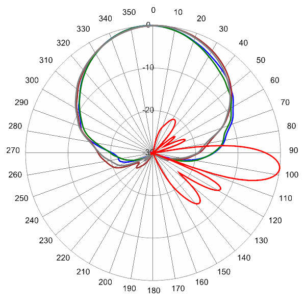
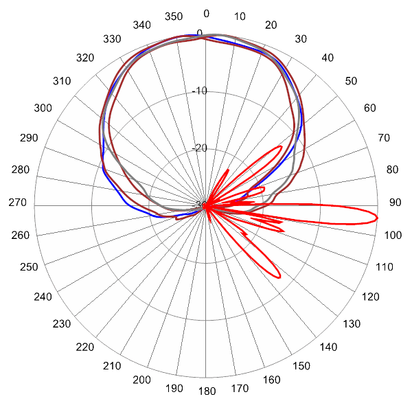
| 645 MHz Azimuth with Elevation 7° | 763 MHz Azimuth with Elevation 7° | |
 |
||
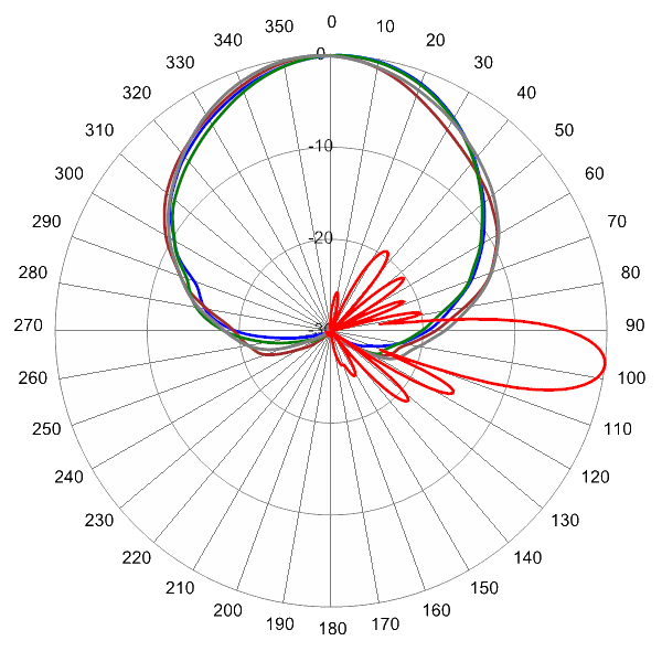
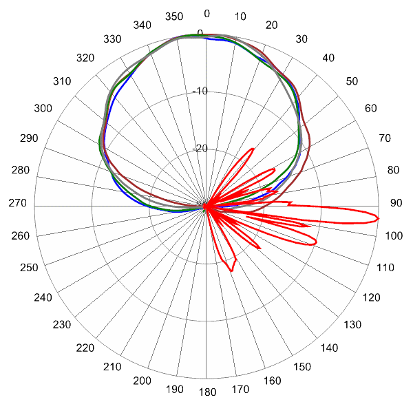
| 824 MHz Azimuth with Elevation 7° |
 |
 |
|
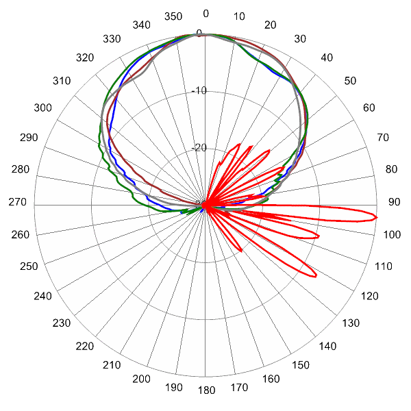
| 1740 MHz Azimuth with Elevation 4° | 1880 MHz Azimuth with Elevation 4° | |
 |
 |
|
| 2155 MHz Azimuth with Elevation 4° | 2540 MHz Azimuth with Elevation 4° |
| MBK-01 | MBK-01 Mounting Kit | |
| MBK-16 | MBK-16 Mounting Kit | |
| BSA-RET400 | Remote Electrical Tilt System (RET) (Type 17 Internal) | |
| SCU-AISG2-P | Portable AISG 2.0 Site Control Unit |