|
|
||||
| Nine Beam 4 x 4 MIMO Special Events Antenna | MBM9F-E3C | |||

 Pattern Viewer
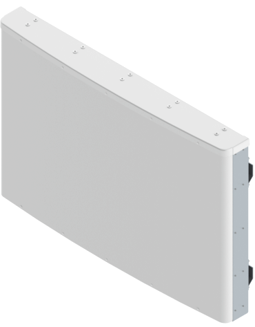 |
|
Mechanical
| Dimensions (L×W×D) | 40.0×60.9×7.5 in (1017×1548×191 mm) |
| Survival Wind Speed | > 150 mph (> 241 kph) |
| Front Wind Load | 521 lbs (2316 N) @ 100 mph (161 kph) |
| Side Wind Load | 71 lbs (316 N) @ 100 mph (161 kph) |
| Equivalent Flat Plate Area | 20.3 ft2 (1.9 m2) |
| Weight * | 119.8 lbs (54.3 kg) |
| Package Dimensions (LxWxD) | 49.1x71.5x15.1 in (1246x1816x384 mm) |
| Package Weight~ | 197.3 lbs (89.5 kg) |
| Connector | 36× 4.3-10 female |
| Mounting Pole | 2x 2 to 5 in (5 to 12 cm) |
| Mounting Pole Spacing | 31.5 in (800 mm) |
| * Weight excludes mounting |
| Bottom View | |
 |
| Connector Spacing | |
 |
| Radio Connects Options | |
 |
 |
 |