

|
|
||||
| Spectrum Sharing 800 MHz Combiner | PFC-800-3xx | |||

 Pattern Viewer
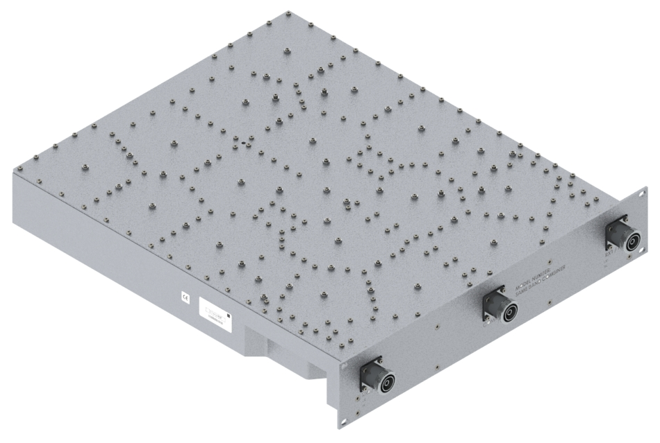 |
|
Overview
|
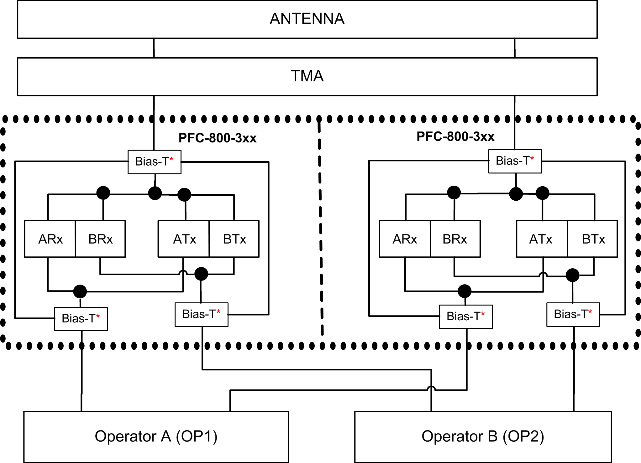
CCI’s narrow guard band, low loss combiner enables two operators or two technologies (eg GSM and LTE) on different sub-bands of the 800 MHz band to be combined onto a single feeder without the insertion loss normally associated with passive combiners. The high power 400 W unit delivers a matched low insertion loss solution for the sharing of common feeder lines and antennas. The unit is a totally passive low loss filter and no power is required. AISG 2.0 compliant DC/AISG pass is provided on either input port utilizing a smart Bias-T. The input ports will sense the DC signal and enable DC/AISG to pass through to the antenna port. The unit is housed in a single rack-mounted 19" by 2U assembly and can be used with other CCI products for further sector enhancement. Outdoor packaging can be provided. Typical deployment uses two identical units per sector, enabling Tx/Rx from both operator BTS ports to combine onto 2 main feeder lines. Technical Description: Internal duplexers deliver signal to independent TX and RX filter combiners with ceramic resonators, enabling a high level of control and performance to maintain good isolation while minimizing insertion loss. Stages are kept to a minimum to maximize power and efficiency. Transmit paths are fully isolated from Receive paths to prevent intermodulation products. |
 |
Electrical
| RF Parameters | Ports | Frequency* | Specification |
| Return Loss | COMMON | OP 1 RX/TX | 18 dB minimum, 20 dB typical |
| OP 2 TX/TX | 18 dB minimum, 20 dB typical | ||
| RX/TX 0 | OP 1 RX/TX | 18 dB minimum, 20 dB typical | |
| RX/TX 1 | OP 2 TX/TX | 18 dB minimum, 20 dB typical | |
| Insertion Loss | RX/TX 0 to COMMON | OP 1 RX & OP 2 RX | 0.3 dB typical 1.0 dB @ band edge |
| RX/TX 1 to COMMON | OP 1 TX & OP 2 TX | 0.4 dB typical 1.2 dB @ band edge |
|
| Isolation | RX/TX 0 to RX/TX 1 | OP 1 RX & OP 2 RX | 18 dB typical 15 dB minimum |
| RX/TX 0 to RX/TX 1 | OP 1 TX & OP 2 TX | 28 dB typical 25 dB minimum |
|
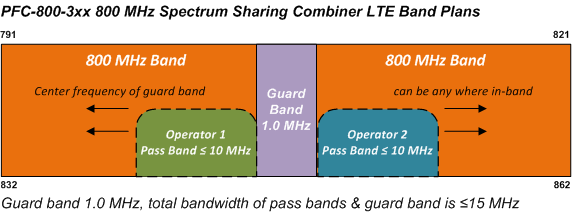
| *See chart below for OP 1 RX/TX and OP 2 RX/TX frequencies | |||
| Model Number | OP 1 (Operator 1) | Guard Band |
OP 2 (Operator 2) | ||
| RX | TX | RX | TX | ||
| PFC-800-301 | 852.0 - 862.0 | 811.0 - 821.0 | 1.0 | 842.0 - 851.0 | 801.0 - 810.0 |
| Contact sales for additional operator frequency combinations, unit is factory settable with guard band ≥ 1.0 MHz, and ≤ 5.0 MHz) | |||||
| General Characteristics | |||||
| Impedance | 50 ohms | ||||
| Continuous Average Power | 400 W max. (all ports) | ||||
| Peak Envelope Power | 2 kW max. (all ports) | ||||
| Intermodulation Performance | <-117 dBm (-160 dBc) typical (2 × +43 dBm tones) all bands | ||||
| DC/AISG Pass any port to Common Port | 3A/AISG signal (2.176 MHz) per AISG 2.0 | ||||
 |


|
|


