

|
|
||||
| Outdoor Low Loss Diplexer | LLC-1721-FTU-0-A2B1-EX | |||

 Pattern Viewer
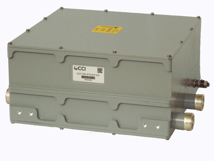 |
|
Overview
|
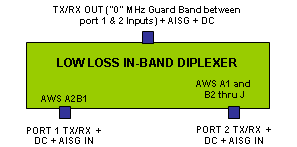
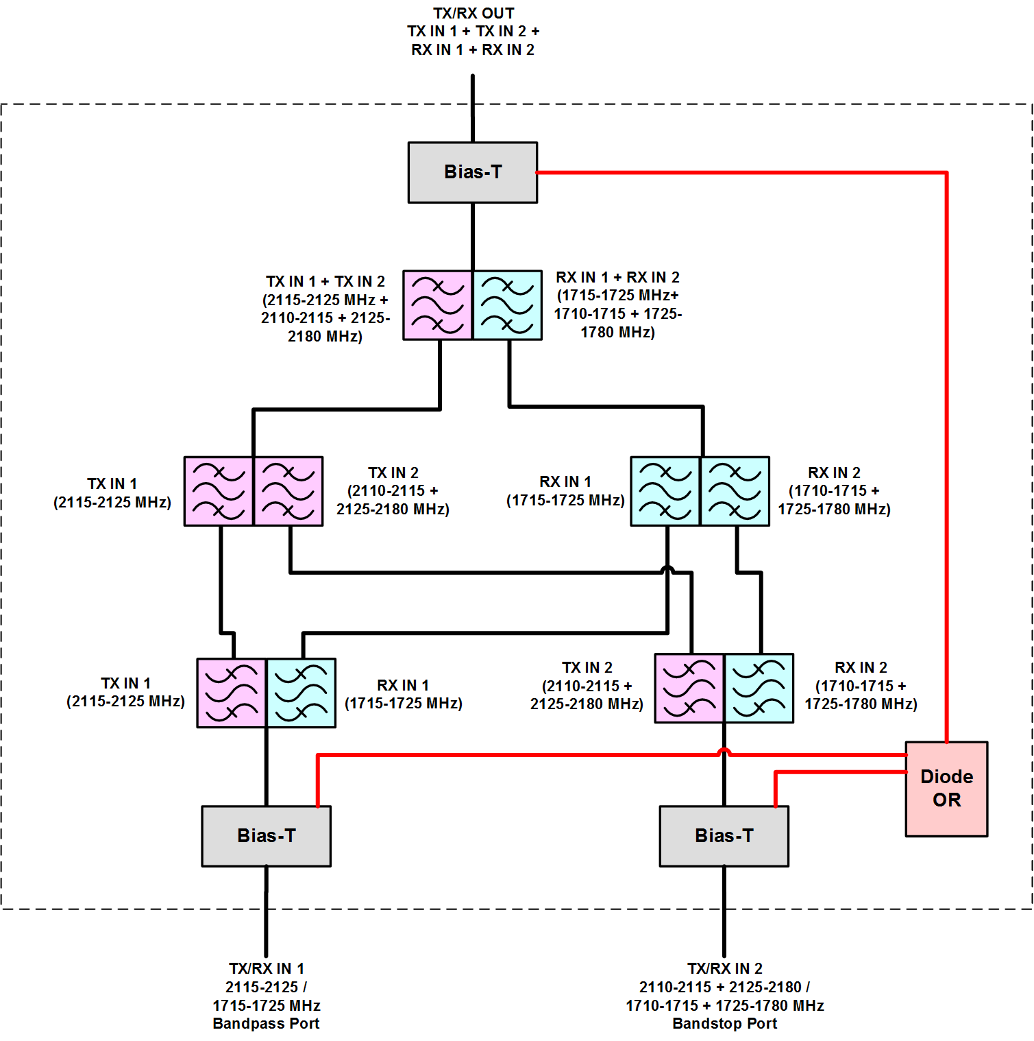
CCI’s AWS In-Band Low Loss Diplexer with a “0” MHz Guard Band combines two UMTS or LTE AWS Base Station sub-band outputs band onto a single feeder without the insertion loss normally associated with hybrid combiners. The unit is fully passive and delivers a matched low insertion loss solution for the sharing of common feeder lines and antennas. The unit is completely passive and provides automatic routing of DC and AISG signals from the individual input ports to the common port. The unit is housed in a weatherproof outdoor enclosure suitable for tower mount application. Technical Description: This In-Band Diplexer allows the TX/RX combining of AWS A2B1 Band with AWS A1 and B2 thru J Bands separated by a “0” MHz Guard Band. Internal duplexers deliver signal to independent Tx and Rx filter combiners, enabling a high level of control and performance to maintain good isolation while minimizing insertion loss. Stages are kept to a minimum to maximize power and efficiency. Transmit paths are fully isolated from Receive paths to prevent intermodulation products. The fully weatherproof tower mount unit incorporates a unique intelligent Bias-T architecture which passes the DC and AISG carrier frequency from any of the input ports to the common port while blocking the DC and AISG signals from being re-injected into the other input ports. The tower mount unit consists of multiple band-pass filters which are all housed in an IP68 immersion proof enclosure, with IP68 immersion proof connectors suited for long-life masthead mounting. The unit provides protection against lightning strikes via a multi-stage surge protection circuit. |
 |
Electrical
| RF Parameters | Ports | Frequency(MHz) | Specification |
| Return Loss | Common and Bandstop | 1710 - 1780 | 18 dB min., 20 dB typ. |
| 2110 - 2180 | 18 dB min., 20 dB typ. | ||
| Bandpass | 1710 - 1780 | 18 dB min., 20 dB typ. | |
| 2110 - 2180 | 18 dB min., 20 dB typ. | ||
| Insertion Loss | Common to Bandpass | 1715 - 1725 | 0.7 dB typ. |
| 2115 - 2125 | 0.7 dB typ. | ||
| Common to Bandstop | 1710 - 1715 | 0.7 dB typ. | |
| 1725 - 1780 | 0.7 dB typ. | ||
| 2110 - 2115 | 0.7 dB typ. | ||
| 2125 - 2180 | 0.7 dB typ. | ||
| Isolation | Bandstop to Bandpass | 1710 - 1715 | ≥30 dB typ. |
| 1715.56 - 1724.44 | ≥30 dB typ. | ||
| 1725 - 1780 | ≥30 dB typ. | ||
| 2110 - 2115 | ≥30 dB typ. | ||
| 2115.56 - 2124.44 | ≥30 dB typ. | ||
| 2125 - 2180 | ≥30 dB typ. |
| General Characteristics | ||
| Impedance | 50 ohms | |
| Guard Band | No additional guard band required beyond the built in guard band for UMTS and/or LTE (10 MHz or greater) | |
| EVM | < 4% over each 3.84 MHz UMTS channel | |
| Group Delay | 100 nS - 190 nS over each 3.84 MHz UMTS channel | |
| Continuous Average Power | 200 W max. (all ports) | |
| Peak Envelope Power | 2 kW max. (all ports) | |
| Intermodulation Performance(all ports) | <-110 dBm (-153 dBc) typical (2 × +43 dBm tones) all bands | |
| DC Pass-Through | Self detecting* | |
| AISG Pass-Through | Follows detected DC* | |
| *If DC is detected for ANT-Tx1/Rx1, then AISG is passed-through as well, and DC is blocked for ANT-Tx2/Rx2 path, and vice versa | ||
 |
|
 |
|
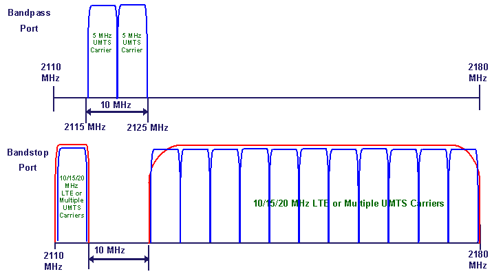
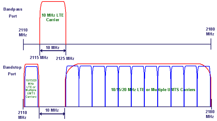
| "0 MHz" Guard Band Low Loss Diplexer Typical Applications for UMTS & LTE |
Mechanical
| Connectors | 3 × 7-16 DIN female |
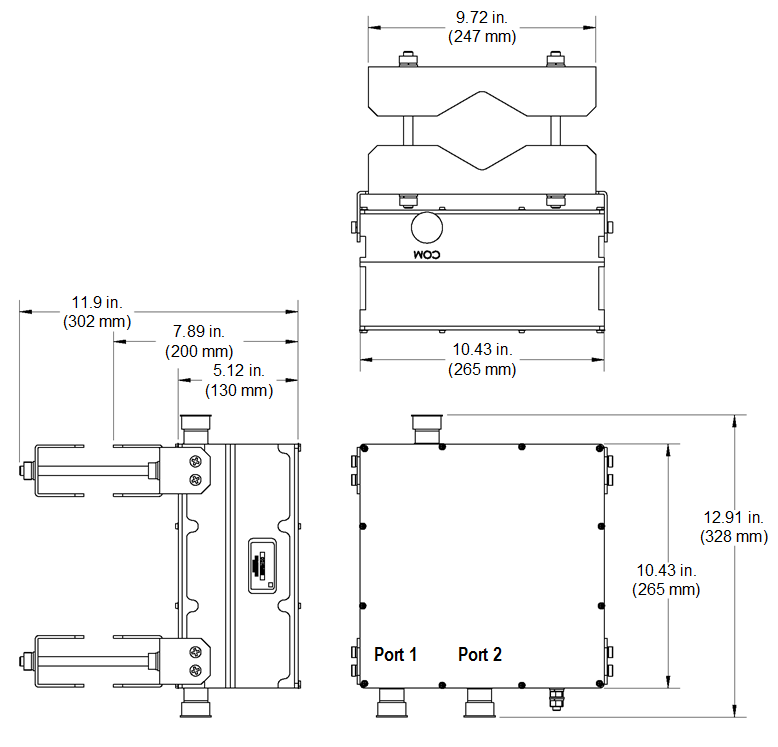
| Dimensions (body only)(H×W×D) | 10.43 × 10.43 × 5.12 in. (265 × 265 × 130 mm) |
| Dimensions (incl. bracket and conn.)(H×W×D) | 10.43 × 12.91 × 11.9 in. (265 × 328 × 302 mm) |
| Weight | 41 lbs (18.6 kg) |
| Mounting | Pole/Wall mounting bracket |
 |
|
| AWS In-Band Low Loss Diplexer Outline Drawing |

|
|


