

|
|
||||
| PCS D,B&E Plus C2 & C3 In-Band Combiner | PFC-1819-DBE-C2C3 | |||

 Pattern Viewer
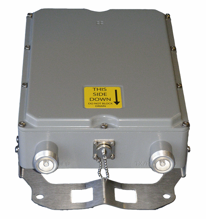 |
|
Overview
|
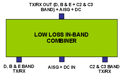
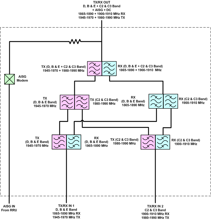
CCI’s Low Loss PCS In-Band Combiner combines two of the PCS (1900 MHz) band Base Station outputs on the D, B & E sub-bands with the C2 & C3 sub-bands onto a single feeder without the insertion loss normally associated with hybrid combiners. The unit is fully passive and delivers a matched low insertion loss solution for the sharing of common feeder lines and antennas. The unit requires no power and provides an AISG port which connects to an AISG Modem that provides DC + AISG signal to power TMA’s and Antennas. The unit is housed in a weatherproof outdoor enclosure suitable for tower mount application. Technical Description: Internal duplexers deliver signal to independent Tx and Rx filter combiners, enabling a high level of control and performance to maintain good isolation while minimizing insertion loss. Stages are kept to a minimum to maximize power and efficiency. Transmit paths are fully isolated from Receive paths to prevent intermodulation products. The tower mount unit consists of multiple band-pass filters and an AISG Modem which are all housed in an IP67 moisture proof enclosure, with IP68 immersion proof connectors suited for long-life masthead mounting. The unit provides protection against lightning strikes via a multi-stage surge protection circuit. |
 |
Mechanical
| Connectors | 3 × 7-16 DIN female; 1× AISG-female |
| Dimensions(body only)(H×W×D) | 10.6 × 7.9 × 2.5 in. (270 × 200 × 65 mm) |
| Dimensions (with brackets)(H×W×D) | 14.3 × 8.3 × 3.5 in. (362 × 211 × 89 mm) |
| Weight with brackets | 12 lbs (5.5 kg) |
| Mounting | Pole/Wall mounting bracket |
 |
|
| PCS D,B & E plus C2 & C3 In-Band Combiner Outline Drawing |

|
|


