

|
|
||||
| PCS A&D Plus E thru G In-Band Combiner | PFC-1819-AD-EG | |||

 Pattern Viewer
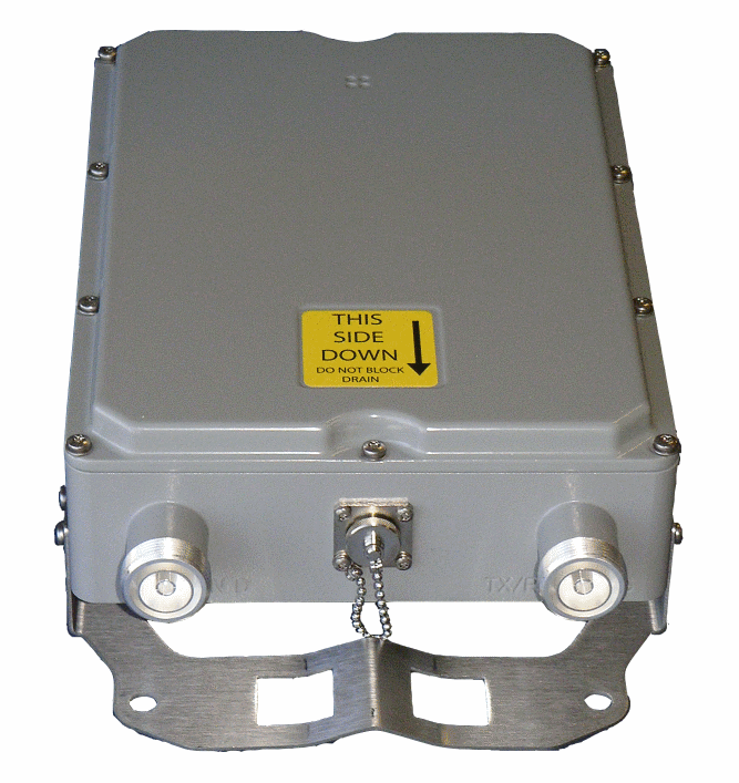 |
|
Overview
|
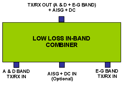
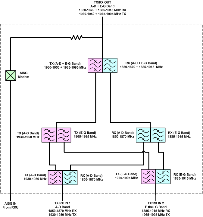
CCI’s Low Loss PCS In-Band Combiner combines two Base Station outputs on the A and D plus E thru G sub-bands of the PCS (1900 MHz) band onto a single feeder without the insertion loss normally associated with hybrid combiners. The unit is fully passive and delivers a matched low insertion loss solution for the sharing of common feeder lines and antennas. The unit requires no power and has a DC Block on the Input ports. Optional AISG port which connects to an AISG Modem that provides DC + AISG signal to power TMA’s and Antennas is available. The unit is housed in a weatherproof outdoor enclosure suitable for tower mount application. Technical Description: Internal duplexers deliver signal to independent Tx and Rx filter combiners, enabling a high level of control and performance to maintain good isolation while minimizing insertion loss. Stages are kept to a minimum to maximize power and efficiency. Transmit paths are fully isolated from Receive paths to prevent intermodulation products. The tower mount unit consists of multiple band-pass filters and an optional AISG Modem which are all housed in an IP67 moisture proof enclosure, with IP68 immersion proof connectors suited for long-life masthead mounting. The unit provides protection against lightning strikes via a multi-stage surge protection circuit. |
 |
Mechanical
| Connectors | 3 × 7-16 DIN female; 1× AISG-female |
| Dimensions(body only)(H×W×D) | 10.6 × 7.9 × 2.5 in. (270 × 200 × 65 mm) |
| Dimensions (with brackets)(H×W×D) | 14.3 × 8.3 × 3.5 in. (362 × 211 × 89 mm) |
| Weight with brackets | 12 lbs (5.5 kg) |
| Mounting | Pole/Wall mounting bracket |
 |
|
| PCS A & D plus E thru G In-Band Combiner Outline Drawing |

|
|


