

|
|
||||
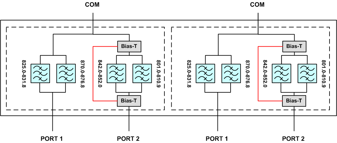
| 800/850 Band Combiner | PFC-885-601 | |||

 Pattern Viewer
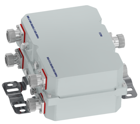 |
|
Mechanical
| Model | Twin |
| Connectors | 6 × 7-16 DIN female (6 x 4.3-10 female optional) |
| Body Dimensions (HxWxD) | 9.37 × 6.89 × 4.41 in. (238 × 175 × 112 mm) |
| Overall Dimensions (HxWxD) | 9.37 × 10.47 × 5.00 in. (238 × 266 × 127 mm) |
| Weight | 13.2 lbs (6.0 kg) |
| Mounting | Pole/Wall mounting bracket |
 |
|
| Twin 800 Band/850 Band Combiner Outline Drawing |


|
|


