|
||||
High Power Directional Coupler | QCO-55-xxxx | |||
![]() |
|
|
|
|
In the Americas | |
Sales | |
+1 (201) 342-3338 phone | |
+1 (201)-342-3339 fax | |
89 Leuning Street | |
South Hackensack, NJ 07606 | |
USA | |
Customer Service | |
+1 (201) 342-3338 phone | |
+1 (201)-342-3339 fax | |
89 Leuning Street | |
South Hackensack, NJ 07606 | |
USA | |
Technical Support | |
+1 (201) 342-3338 phone | |
+1 (201)-342-3339 fax | |
89 Leuning Street | |
South Hackensack, NJ 07606 | |
USA | |
|
||||
High Power Directional Coupler | QCO-55-xxxx | |||
![]() |
|
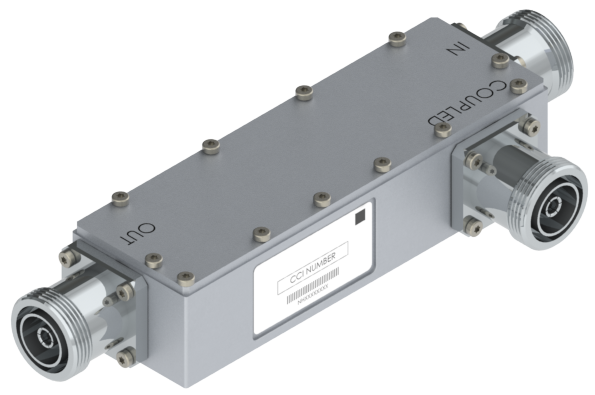
CCI’s QCO-55 series of outdoor directional couplers cover a broad frequency range from 370 to 3600 MHz, while delivering high power performance of up to 750 Watts at the input port. Each model has a nominal coupling value with very low insertion loss and excellent return loss performance. The units are offered in a wide range of coupling values and are ideal for optimizing RF power distribution, which is often required for distributed antenna systems (DAS). The extremely wide frequency range of the couplers enables their use with multiband and broadband antennas as well as a both active and passive DAS systems. The CCI couplers are also rated for outdoor use; this along with the high power handling makes them well-suited for use with wireless base stations. The design of CCI's directional couplers provides for extremely low insertion loss and excellent PIM performance. These units are constructed with a weatherproof aluminum IP67 rated housing and with IP67 immersion rated connectors which enhances the overall reliability. CCI filter and combiner products are designed and produced to ISO 9001 certification standards for reliability and quality at our state-of-the-art engineering and manufacturing facilities. |
RF Parameter | ||||
Model Number | QCO-55-06Fx | QCO-55-08Fx | QCO-55-10Fx | QCO-55-13Fx |
Coupling Values 555 - 3600 MHz | 6.0 ±1.0 dB | 8.0 ±1.0 dB | 10.0 ±1.0 dB | 13.0 ±1.0 dB |
Coupling Values 370 - 555 MHz | 8.0 ±2.0 dB | 10.0 ±2.0 dB | 12.0 ±2.0 dB | 15.0 ±2.0 dB |
Insertion Loss | 1.7 dB | 1.05 dB | 0.7 dB | 0.4 dB |
RF Parameter | ||||
Model Number | QCO-55-15Fx | QCO-55-20Fx | QCO-55-30Fx | QCO-55-40Fx |
Coupling Values 555 - 3600 MHz | 15.0 ±1.0 dB | 20.0 ±1.0 dB | 30.0 ±1.0 dB | 40.0 ±1.0 dB |
Coupling Values 370 - 555 MHz | 17.0 ±2.0 dB | 22.0 ±2.0 dB | 32.0 ±2.0 dB | 42.0 ±2.0 dB |
Insertion Loss | 0.3 dB | 0.2 dB | 0.16 dB | 0.15 dB |
General Characteristics | ||||
Directivity | ≥ 20 dB typical | |||
Return Loss | 18 dB minimum, 20 dB typical | |||
Continuous Average Power | 750 W at the input port | |||
Peak Envelope Power | 7.5 kW max. | |||
Impedance | 50 ohms | |||
Intermodulation Performance |
≤ -117 dBm (-160 dBc) at 2 × +43 dBm tones |
Model | QCO-55-xxF1 | QCO-55-xxF2 |
Connectors | 7-16 DIN-Female × 3 | 4.3-10-Female × 3 |
Dimensions enclosure (H×W×D) | 156 x 49.4 x 37.0 mm (6.14 x 1.94 x 1.45 in.) |
156 x 49.4 x 37.0 mm (6.14 x 1.94 x 1.45 in.) |
Weight | 0.770 Kg (1.70 lbs) | 0.511 Kg (1.13 lbs) |
![]() |
||
High Power Coupler with DIN 7/16 Female Connector (QCO-55-xxF1) Outline Drawing |
QCO-55-06Fx | Ultra-broadband High Power 6dB Coupler |
QCO-55-08Fx | Ultra-broadband High Power 8dB Coupler |
QCO-55-10Fx | Ultra-broadband High Power 10dB Coupler |
QCO-55-13Fx | Ultra-broadband High Power 13dB Coupler |
QCO-55-15Fx | Ultra-broadband High Power 15dB Coupler |
QCO-55-20Fx | Ultra-broadband High Power 20dB Coupler |
QCO-55-30Fx | Ultra-broadband High Power 30dB Coupler |
QCO-55-40Fx | Ultra-broadband High Power 40dB Coupler |
Option (-x) | Description |
-1 | with DIN 7-16 connector |
-2 | with 4.3-10 connector |
Safety | EN 60950-1, UL 60950-1 |
Emission | EN 55022 |
Immunity | EN 55024 |
Environmental | IEC 60068-2-1, IEC 60068-2-2, IEC 60068-2-5, IEC 60068-2-6, IEC-60068-2-11, IEC 60068-2-14, IEC 60068-2-18, IEC 60068-2-27, IEC 60068-2-29, IEC 60068-02-30, IEC 60068-2-52, IEC 60068-2-64, GR-63-CORE 4.3.1, EN 60529 IP67 & IP68 |
|
|
![]() | FREQUENCY BAND | |
![]() | DC-617MHz |
![]() | 617-698 MHz (600 Band) |
![]() | 698-798 MHz (700 Band) |
![]() | 790-862 MHz (LTE 800) |
![]() | 806-869 MHz (SMR 800) |
![]() | 816-869 MHz (SMR 800ABC) |
![]() | 824-894 MHz (Cellular) |
![]() | 880-960 MHz (GSM 900) |
![]() | 1427-1518 MHz (IMT 1400) |
![]() | 1710-1880 MHz (DCS) |
![]() | 1695-1780/2110-2180 MHz (AWS) |
![]() | 1850-1995 MHz (PCS) |
![]() | 1920-2170 MHz (IMT 2100) |
![]() | 2305-2360 MHz (WCS) |
![]() | 2300-2400 MHz (TDD) |
![]() | 2496-2690 MHz (BRS) |
![]() | 2570-2620 MHz (TDD) |
![]() | 2500-2570/2620-2690 MHz (FDD) |
![]() | 3300-3800 MHz |
![]() | 5150-5925 MHz |