|
|
||||
| Low Loss Combiner | LLC-850C-IN | |||
 |
|
Overview
|
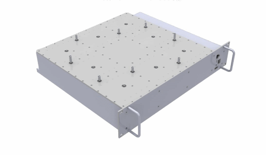
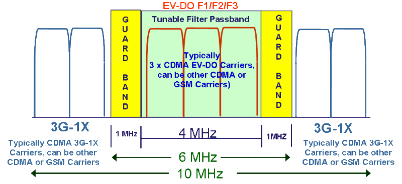
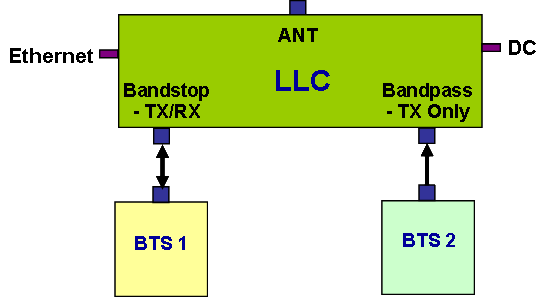
CCI’s Remote Tunable Narrow Guard Band Filter-Combiner (LLC) combines Cellular Band signals onto a single feeder without the insertion loss normally associated with passive combiners. This new highly compact model reduces the guard band requirement to only 500KHz, restoring lost spectrum associated with previous units. A precisely matched filter which is wide enough for three (3) CDMA carriers allows the carriers to be positioned anywhere in the band and provides high rejection of unwanted spurious emissions and noise. Transmit paths are fully isolated to prevent intermodulation products. Note that any technology (including GSM/UMTS, GSM/CDMA, CDMA/CDMA, CDMA/UMTS or UMTS/UMTS) can be combined when utilizing this LLC. However, please note that there is a model specifically for use with CDMA carriers, and is better suited for combining CDMA and other technologies. Multiple units can be cascaded for deployment of additional channels. When not tuning, no power is required, effectively becoming a pure passive low-loss filter combiner. Control is via TCP/IP or Ethernet requiring only a web browser. All software is resident internally, no extra software or controller is required. Note that the Bandpass port “only” passes Tx signals, but the Bandstop port is fully duplexed and passes Tx/Rx signals. The unit is housed in a single rack-mounted 19” by 2U assembly and can be used with CCI SCPA’s for further feeder line reduction. |
Electrical
| RF Parameters | Ports | Frequency(MHz) | Specification |
| Return Loss | Bandstop TX/RX | 869 - 894 | 18 dB min. |
| Bandpass TX Only | 869 - 894 | 18 dB min. | |
| ANT | 869 - 894 | 18 dB min. | |
| Insertion Loss | Bandstop TX/RX to ANT | 869 to (fc - 2.0) | 0.5 dB typ. |
| (fc + 2.0) to 894 | 0.5 dB typ. | ||
| Bandpass TX Only to ANT | (fc - 2.0) to (fc + 2.0) | 0.5 dB typ. | |
| Isolation | Bandstop TX/RX to Bandpass TX Only | 869 to (fc - 2.0) | ≥45 dB typ. |
| (fc - 2.0) to (fc + 2.0) | ≥27 dB typ. | ||
| (fc + 2.0) to 894 | ≥45 dB typ. | ||
| Tuning Range | Any 4 MHz segment (center frequency - fc) in 869 - 894 MHz | ||
| General Characteristics | |
| Impedance | 50 ohms |
| Guard Band | 1 MHz each side of passband |
| Group Delay variation | 50 nS typ. |
| Continuous Average Power | 500 W max. (all ports) |
| Peak Envelope Power | 2 kW max. (all ports) |
| IMD | <-110 dBm (-153 dBc) typical (2 × +43 dBm tones) all bands |
 |
|
Mechanical
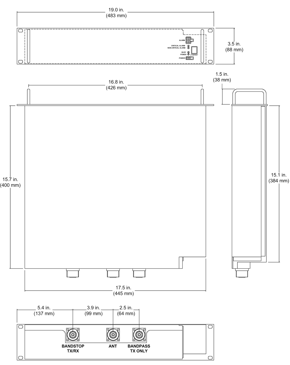
| Connectors | 3 × 7-16 DIN female |
| Data Connection | RJ45 Ethernet |
| Alarm Connection | 6 pin Molex connector (4.2 mm) |
| Power Connection | 2 pin Molex connector (4.2 mm) |
| DC Power Requirement | 2A @ +24VDC (only required when tuning) |
| DC Voltage | ±18 to ±76 VDC |
| Dimensions (incl. connectors)(H×W×D) | 3.5 × 19 × 16.995 in. (88.9 × 482.6 × 431.67 mm) |
| Dimensions (incl. connectors and handles)(H×W×D) | 3.5 × 19 × 18.175 in. (88.9 × 482.6 × 461.65 mm) |
| Weight | 28.5 lbs (12.9 kg) |
 |
|
| Low Loss Combiner Outline Drawing |
Product Information
| LLC-850C-IN Dimension Drawing | ||
| LLC-850 Operating Instructions |
|
|


 Pattern Viewer


