|
|
||||
| Five-Beam Special Events Multibeam Antenna | MBA5F-U3A | |||

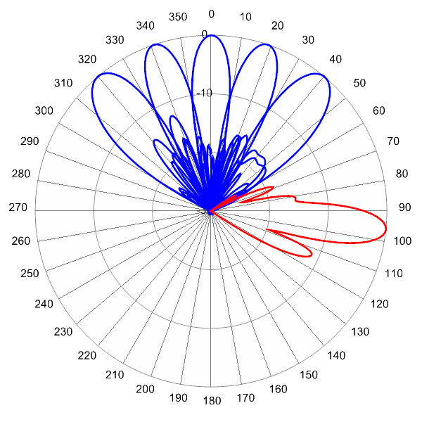
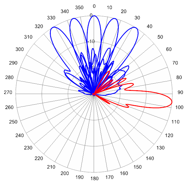
 Pattern Viewer
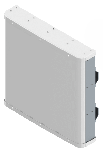 |
|
Mechanical
| Dimensions (L×W×D) | 33.0×33.4×6.5 in (839×849×165 mm) |
| Survival Wind Speed | > 150 mph (> 241 kph) |
| Front Wind Load | 236 lbs (1048 N) @ 100 mph (161 kph) |
| Side Wind Load | 50 lbs (223 N) @ 100 mph (161 kph) |
| Equivalent Flat Plate Area | 9.2 ft2 (0.9 m2) |
| Weight * | 50.7 lbs (23.0 kg) |
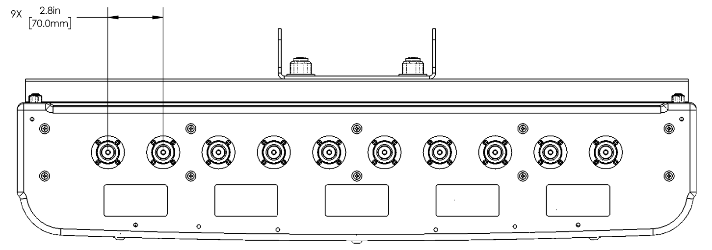
| Connector | 10 × 7-16 DIN female long neck or 4.3-10 female |
| Mounting Pole | 2 to 5 in (5 to 12 cm) |
| * Weight excludes mounting |
| Bottom View | |
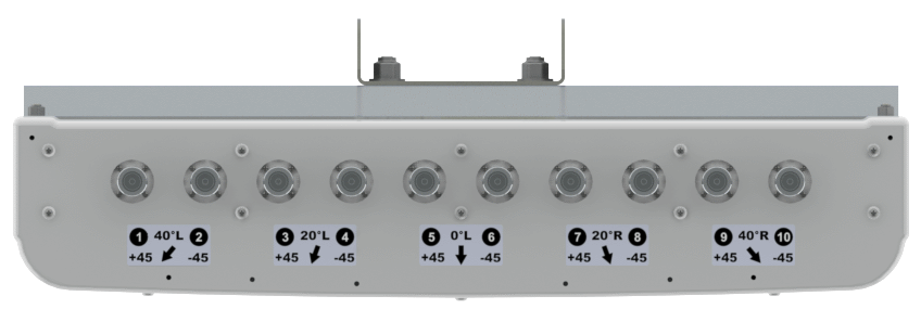 |
| Connector Spacing | |
 |