|
|
||||
| Wideband Six-Beam Special Events Antenna | MBA6F-W3A | |||

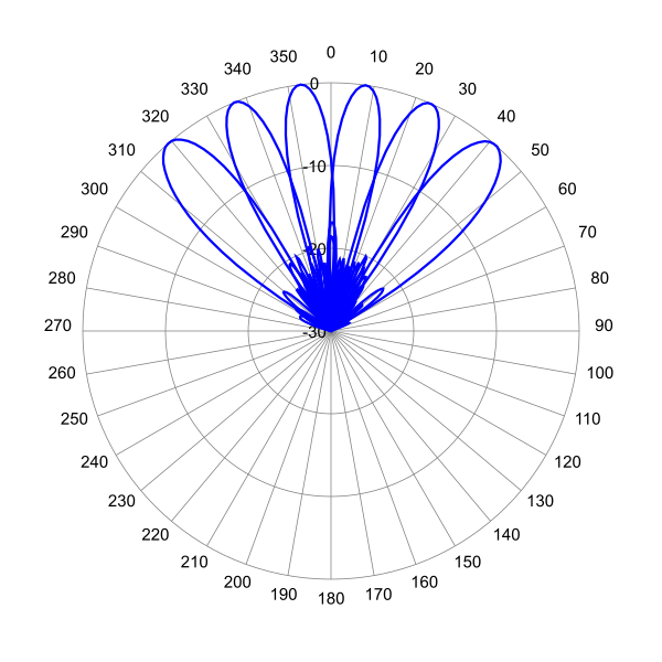
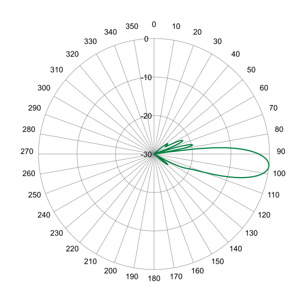
 Pattern Viewer
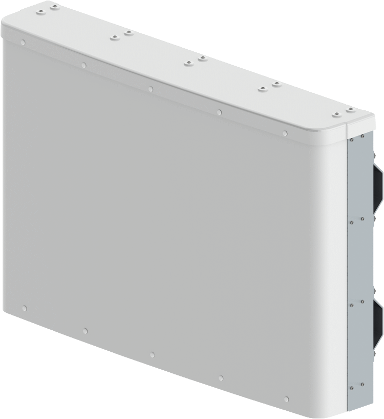 |
|
Mechanical
| Dimensions (L×W×D) | 27.9×41.7×7.5 in (708×1058×191 mm) |
| Survival Wind Speed | > 150 mph (> 241 kph) |
| Front Wind Load1 | 214 lbf @ 100 mph 953 N @ 161 kph |
| Side Wind Load1 | 13 lbf @ 100 mph 60 N @ 161 kph |
| Effective Projective Area (EPA), Front1 | 8.6 ft2 (0.8 m2) |
| Weight * | 58.6 lbs (26.6 kg) |
| Package Dimensions (LxWxD) | 35.1×51.5×15.0 in (891×1307×380 mm) |
| Package Weight | 93.0 lbs (42.2 kg) |
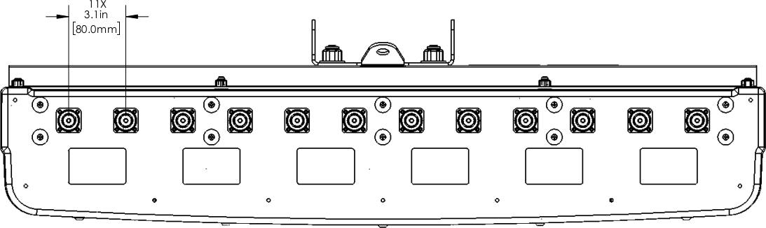
| RF Connector | 12 × 7-16 DIN female long neck or 12 × 4.3-10 female |
| Mounting Pole | 2 to 5 in (5 to 12 cm) |
| 1Windload values calculated using CFD analysis * Weight excludes mounting kit |
|
| Bottom View | |
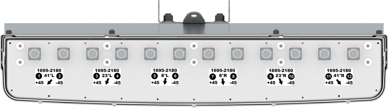 |
| Connector Spacing | |
 |