|
|
||||
| Six/Three-Beam Special Events Antenna | MBA6-9F-BW-H3 | |||

 Pattern Viewer
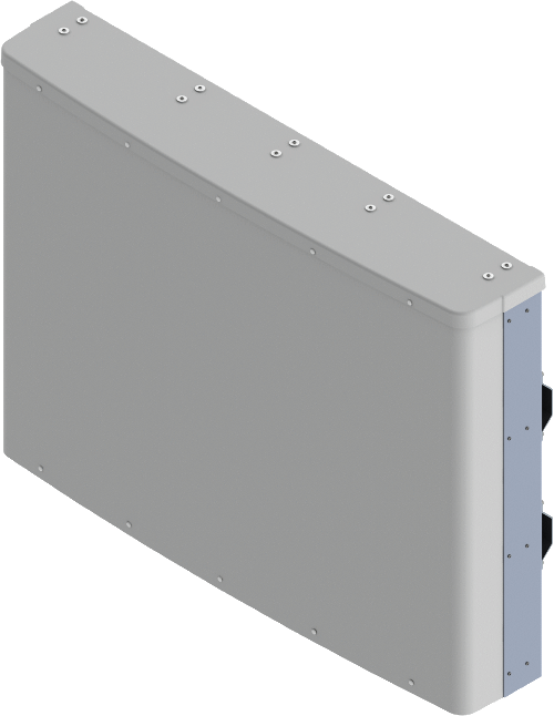 |
|
Mechanical
| Dimensions (L×W×D) | 40.8×55.0×10.2 in (1036×1398×259 mm) |
| Survival Wind Speed | > 150 mph (> 241 kph) |
| Front Wind Load1 | 425 lbf @ 100 mph 1892 N @ 161 kph |
| Side Wind Load1 | 37 lbf @ 100 mph 166 N @ 161 kph |
| Effective Projective Area (EPA), Front1 | 17.2 ft2 (1.6 m2) |
| Weight * | 115 lbs (52 kg) |
| Connector | 18 × 7-16 DIN female long neck |
| Mounting Pole | 2x 2 to 5 in (5 to 12 cm) |
| Mounting Pole Spacing | 38.4 in (976 mm) |
| 1Windload values calculated using CFD analysis * Weight excludes mounting |
|
| Bottom View | ||
 |
||
| Connector Spacing | ||
 |
||