|
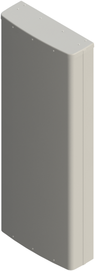
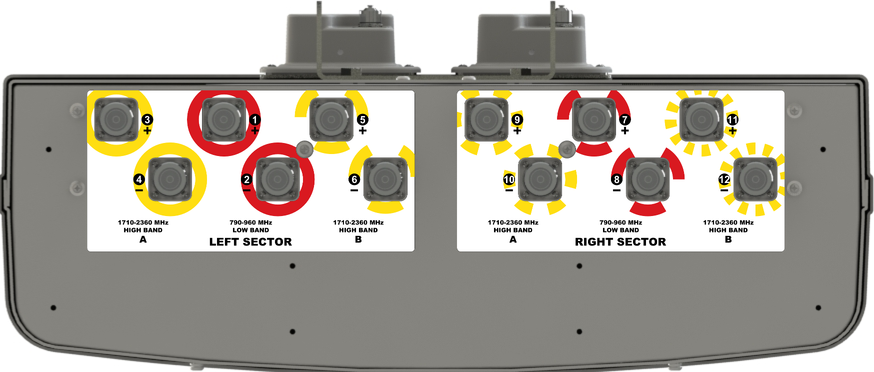
The CCI multi-band Twin HexPort Bi-SectorTM array is a dual beam antenna with full SMR 800, Cellular, AWS, PCS and WCS band coverage. This six foot (1.8 m) antenna can be configured to deploy two asymmetric 33° beams each containing two low band ports covering 790-960 MHz and four high band ports covering 1710-2360 MHz in a single enclosure. With four high band ports in each sub-beam this antenna is ideally suited for implementation of 2x4 and 4x4 MIMO system configurations. The CCI multi-band Bi-SectorTM provides the capability to deploy two sectors of 4×4 Multiple-input Multiple-output (MIMO) in the high band. The Remote Electrical Tilt (RET) feature allows separate tilt control for the high and low band in each 33° beam, enabling maximum flexibility in network deployment.
CCI's unique patented bi-sector technology provides optimized overlap between the pairs of asymmetric beams, lowers soft handover losses in LTE, UMTS/HSPA+ and CDMA/EVDO systems, while minimizing interference between sectors. Fast roll-off of each of the outer beams and high front-to-back ratios ensure reduced interference. This patented approach enhances data transfer rates within LTE, UMTS and EVDO network sectors and addresses “hotspots” in mobile wireless operator networks.
The single panel design of the Bi-SectorTM Array offers the opportunity to reduce antenna count and directly replaces an existing 65° antenna without mount changes and avoids costly leasing and zoning changes. The enhanced coverage matches the existing sector footprint and minimizes the need for optimization and adjacent site changes, providing operators with significant CAPEX and OPEX cost savings.
CCI antennas are designed and produced to ISO 9001 certification standards for reliability and quality in our state-of-the-art manufacturing facilities.
|


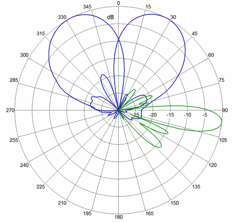
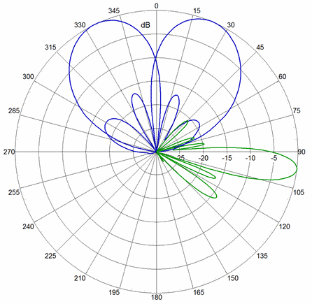
 Pattern Viewer
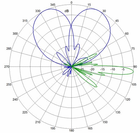