| |
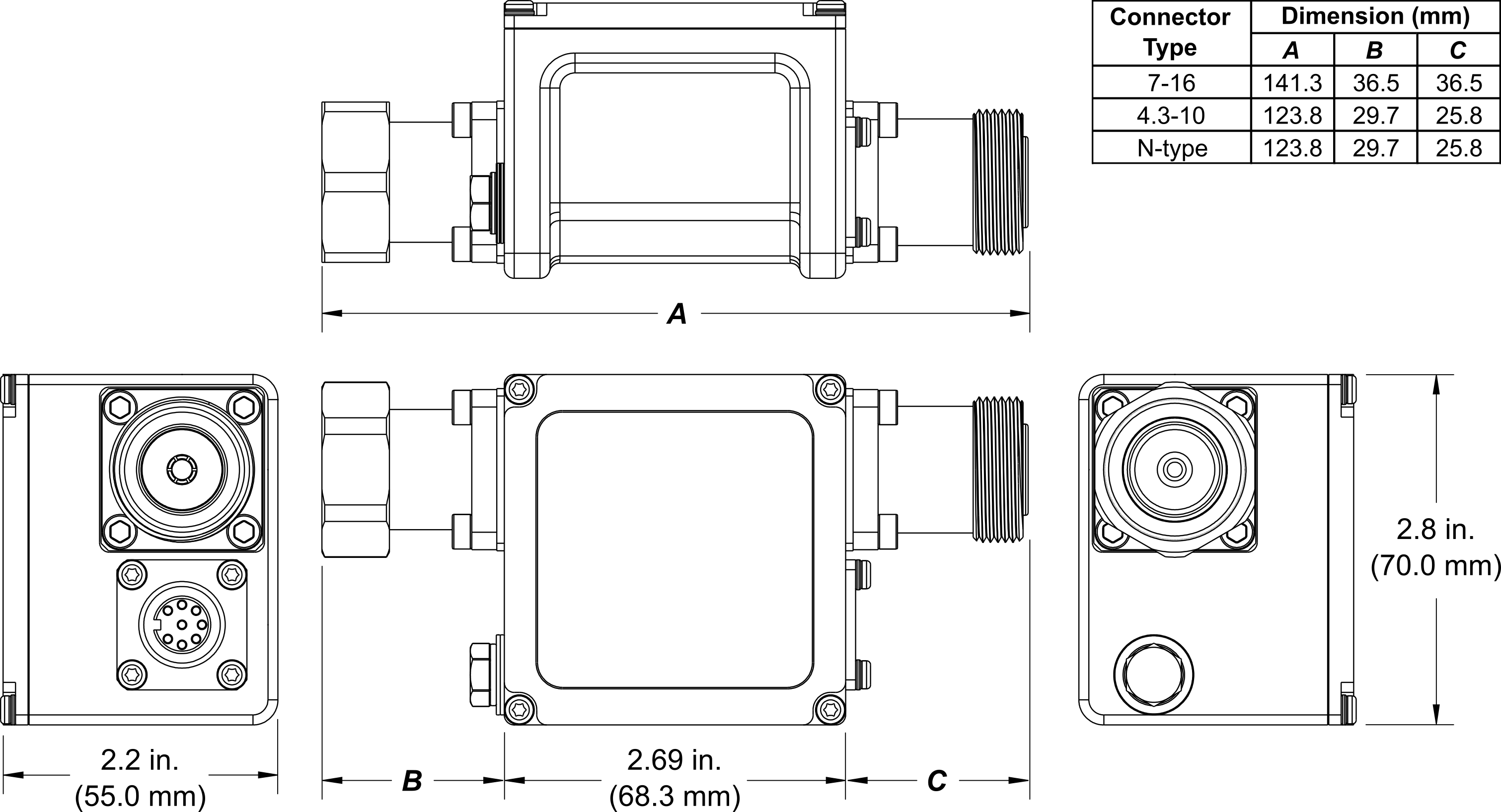
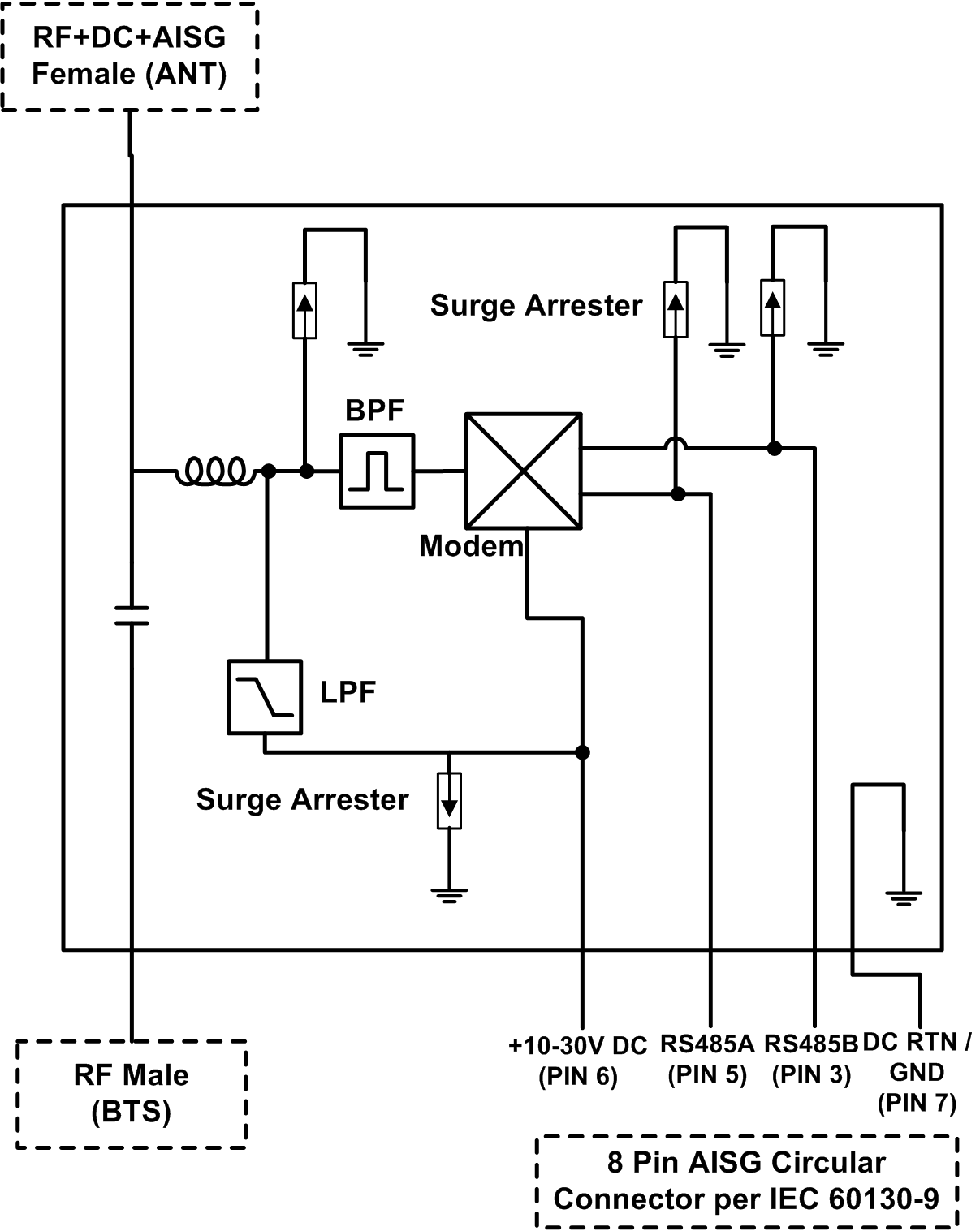
Communication Components, Inc. (CCI) Bias-T’s are designed to combine the DC Bias and AISG compliant communication link provided by the “Site Control Unit” (SCU) with the RF signal from other equipment onto the center conductor of the feeder line. By providing control interfaces which are AISG 2.0 compatible to and from the “Site Control Unit,” the Bias-T’s can provide AISG control signals to AISG 2.0 compliant equipment including Tower Mounted Amplifiers (TMAs) and Antennas equiped with Remote Electrical Tilt Actuators via the RF Feeder Lines. The Bias-T also provides surge protection in case of lightning strikes or other sources of surges. The Bias-T offers a choice of either 7-16, 4.3-10 or N-Type RF connectors. The standard Bias-T has a Male RF connector at the RF Input port, an 8 pin AISG Compliant (per IEC 60130-9) male circular connector at the DC Input port, and a Female RF connector at the combined RF, DC and AISG Signal output port. The unit is fully rated for outdoor deployment.
Technical Description:
The standard Bias-T consists of Male BTS Input (RF) and a Female ANT Output (RF + DC+AISG signal) connector, as well as an 8-Pin AISG-compliant Female Circular connector for the DC Bias Input point. A reverse gender Bias-T is also available where the RF port genders are reversed (Female BTS Input (RF) to Male ANT (RF+DC+AISG signal). Similarly, a Female only RF port Bias-T (Female BTS Input (RF) to Female ANT Output (RF+DC_AISG signal) is also available. The 8-pin AISG connector supplies +10-30V DC, DC Return/Ground, RS485A, and RS485B to the Bias-T in order to provide the application of bias for the TMA, a power source for the RS485 Modem within the Bias-T, the appropriate RS485 signal paths and grounding/DC return as required. The unit also provides protection against lightning strikes via a surge protection circuit. The Bias-T is fully tested for outdoor applications, being housed in an IP67 rated enclosure with IP67 rated connectors suited to long-life indoor & outdoor mount.
An optional indoor Site Control Unit (SCU) is available to power up to 32 AISG modules per sector and to provide all the monitoring and alarm functions for the system. The SCU is housed in a single (1U) 1.75” x 19” rack and contains dual redundant power supplies that provide a regulated DC supply voltage for all AISG tower mounted components such as TMA’s and Antenna’s.
|


 Pattern Viewer